
Alright, suppose you were like me and bought some servers for virtual networking as well as some old routers. Now you see all those RJ45 ports (or even SFP cages if you’re rich) and wonder: Can I connect them and make it work? I am here for happy news: YES, you can and should totally do it. Why? Here are some resons for a hybrid lab:
- You don’t need to buy expensive routers (MX, NCS, ASR) because you can emulate them and still use cheaper, ebay bought edge routers.
- You can basically build your own ISP at home.
- It is absolutely fun!
I hope I could convince you to follow along for the ride.
How does interconnecting work?
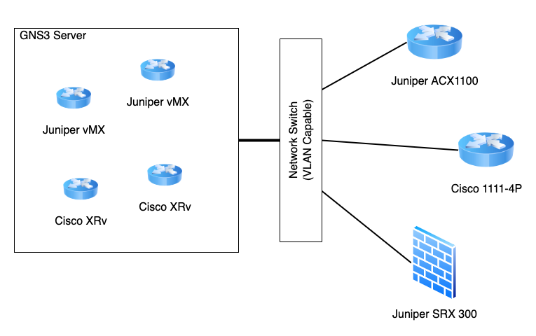
This is a schematic overview of how we will be doing this. We will use one of our additional NICs on the GNS3 server, connect a VLAN capable network switch to it and switch VLANs to all of our appliances. This way, we can make sure they can communicate with one another.
To use these VLANs inside GNS3, we will mak use of the cloud feature, but more on that later on.
Setting up VLAN interfaces on the server
To set up VLAN interfaces on our GNS3 server, we first need to enable the 8021q kernel module (8021q stands for 802.1Q). This is done the following way:
jonathan@gns02:~$ sudo modprobe 8021q

jonathan@gns02:~$ lsmod | grep 8021q
8021q                  40960  0
garp                   16384  1 8021q
mrp                    20480  1 8021q
If the second command gives you some output, you are ready to rumble. You need to create the VLAN interfaces inside your network configuration. Depending on your host OS, this process differs. In my case (Debian 11), it is done by adding a few lines to the /etc/network/interfaces configuration file. Let us create the VLANs 3000 – 3005, which should give us plenty to start with:
auto eno1.3000
iface eno1.3000 inet manual
	vlan-raw-device eno1

auto eno1.3001
iface eno1.3001 inet manual
	vlan-raw-device eno1

auto eno1.3002
iface eno1.3002 inet manual
	vlan-raw-device eno1

auto eno1.3003
iface eno1.3003 inet manual
	vlan-raw-device eno1

auto eno1.3004
iface eno1.3004 inet manual
	vlan-raw-device eno1

auto eno1.3005
iface eno1.3005 inet manual
	vlan-raw-device eno1
As you can see, the configuration for a single interface is quite simple. In my case, I use the eno1 interface, which is not used at the moment. If you want to add more VLANs, just expand this configuration. If you want to change the VLAN IDs, just adjust the numbers (but please remember, VLAN IDs are only valid from 1-4094).
In order to use these interfaces, you have to bring them up. One way could be the ifup command:
jonathan@gns02:~$ sudo ifup eno1.3000
jonathan@gns02:~$ sudo ifup eno1.3001
jonathan@gns02:~$ sudo ifup eno1.3002
jonathan@gns02:~$ sudo ifup eno1.3003
jonathan@gns02:~$ sudo ifup eno1.3004
jonathan@gns02:~$ sudo ifup eno1.3005
jonathan@gns02:~$
Another alternative is to restart the networking service. However, I would be very careful, as misconfiguration can stop the service from working and essentially locks you out from it.
Adding VLAN Interfaces to GNS3
Making GNS3 aware of your interfaces is quite simple. If you followed the original tutorial for setting GNS3 up, Part 3, you simply need to restart GNS3.
If you have made some configuration changes and use a custom gns3_server.conf file, you will firstly need to manually add your interfaces to this file.
Using VLAN Interfaces inside a GNS3 project
If you now want to use one of your newly created VLAN interfaces inside your GNS3 project, you simple add the Cloud node to your project:
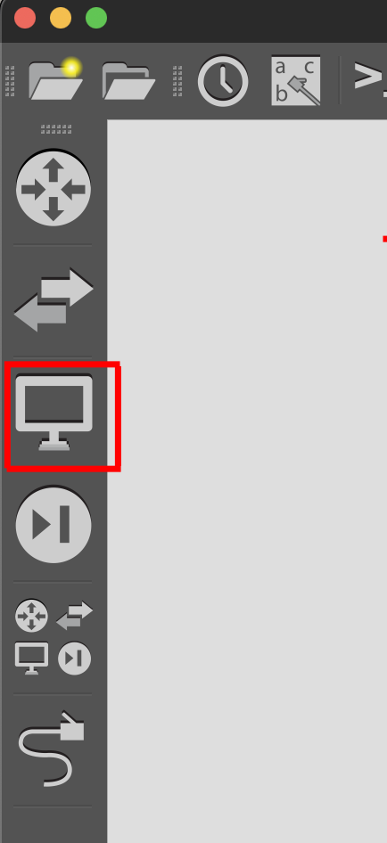
Step 1: Open the End Devices tab inside GNS3
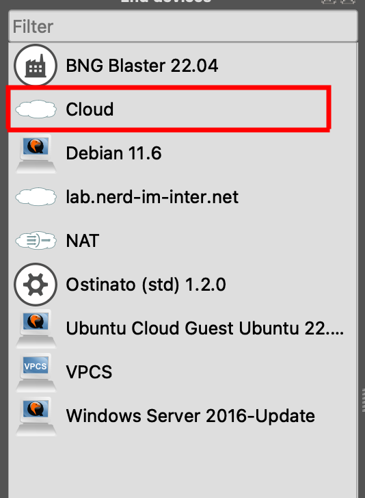
Step 2: Locate the Cloud Device
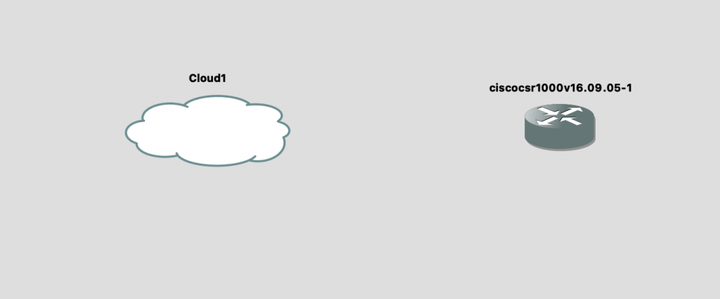
Step 3: Placing the Cloud into the project
Step 4: Connecting your ports
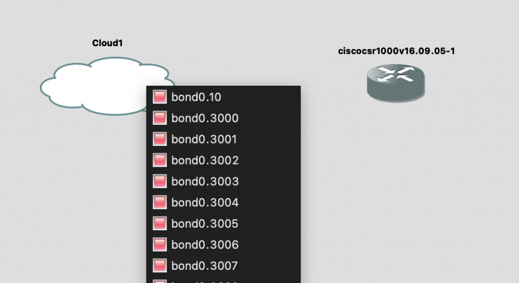
Please don’t be confused by my port names. As this is a screenshot from my production server, where I use bundle interfaces to connect to my switching fabric, the ports are named bond0.XXXX. If you do not see your VLAN interfaces inside of this list, you may have a gns3_server.conf file but you don’t know about it. Here is a tutorial on how to find this file: https://docs.gns3.com/docs/using-gns3/administration/gns3-server-configuration-file/
Bringing the VLAN to a real world device
In my case, I have a switching fabric, which essentially just means that there are a few switches behaving like one big virtual switch. My GNS3 server is available at the interface ae1:
master@fabric> show configuration interfaces ae1
aggregated-ether-options {
    lacp {
        active;
        periodic fast;
    }
}
unit 0 {
    family ethernet-switching {
        port-mode trunk;
        vlan {
            members [ LAB-10 GNS3-3000 GNS3-3001 GNS3-3002 GNS3-3003 GNS3-3004 GNS3-3005 GNS3-3006 GNS3-3007 GNS3-3008 GNS3-3009 GNS3-3010 GNS3-3011 GNS3-3012 GNS3-3013 GNS3-3014 GNS3-3015 GNS3-3016 GNS3-3017 GNS3-3018 GNS3-3019 GNS3-3020 ];
        }
    }
}
As you can see, I already created all my VLANs on the fabric and already tagged the VLANs accordingly. This makes it very simple for me to interconnect devices. Inside GNS3, I connect interface bond0.3010 to a virtual Cisco router. By the name of the interface, I know that VLAN 3010 (or GNS-3010 as I named them) is the VLAN I want to tag to my real router, a Cisco 1111 in this case.
master@fabric> show configuration interfaces ge-1/0/3
description "## CBL-085 | cisco-1111-1.lab | Gi0/1/1";
unit 0 {
    family ethernet-switching {
        port-mode trunk;
        vlan {
            members GNS3-3010;
        }
    }
}
So, in theory, if I configure VLAN 3010 on the Cisco 1111 (because the interface towards it is a trunk interface), I should be able to communicate with my virtual Cisco router. Let’s try that.
Configuring the routers
My virtual router will get the following configuration:
interface GigabitEthernet1
 ip address 192.168.7.1 255.255.255.0
 negotiation auto
 no mop enabled
 no mop sysid
end
The Cisco 1111 will get a slightly more complicated configuration, but only because the port used is an L2 port instead of an L3 port like the virtual one:
vlan 3010
!
interface GigabitEthernet0/1/1
 switchport trunk allowed vlan 3010
 switchport mode trunk
!
interface Vlan3010
 ip address 192.168.7.2 255.255.255.0
end
So, drumroll please:
cisco-1111-1.lab#ping 192.168.7.1
Type escape sequence to abort.
Sending 5, 100-byte ICMP Echos to 192.168.7.1, timeout is 2 seconds:
.!!!!
Success rate is 80 percent (4/5), round-trip min/avg/max = 1/22/88 ms
cisco-1111-1.lab#
As you can see, after a short wait, I am able to ping my virtual router, which means that my real world router can talk to the virtual one. Isn’t that great?
Other usecases
Another usecase for this would be to make your virtul routers manageable via SSH. Naturally, the Cloud Device in GNS3 will also show your interface that you use for communicating with the server itself. If you connect a virtual switch to it, you can connect the management interfaces of your virtual appliances to it and give them IP-addresses from your home or lab network, thus making you able to SSH into these devices.
Alright folks, this was today’s post. I hope you enjoyed it and could recreate everything inside your own homelabs. If not, feel free to reach out to me via the comments section! Until next time.